Note: this was going to be one post but it’s ballooned into a huge thing so this is one of several which will be posted over the next few days. Stay tuned!
So you’ve got a nice Arduino board for experimentation and you’ve built a circuit on a breadboard which you’d like to make permanent.
It’s expensive (and overkill) to use a new arduino each time you build a new circuit you want to keep. Here’s how you can easily build an arduino-compatible board, from complete scratch, for a few pounds/dollars/euros so you can keep your real arduino for experimenting with…
I assume you already have an arduino (we’ll need it to program the arduino bootloader on the ATMega chip). You can get ATMega chips with the arduino boot loader burned in already, but I’ve even saved that expense and used a stock Atmel ATMega168-20PU (available in the UK for about £3, I got mine from http://www.bitsbox.co.uk/), and we’ll cover burning the boot loader in a later post.
We start with the vero board (AKA stripboard). Stripboard is simply a board with copper tracks running across it, with pre-drilled holes in it. It’s simply a permanent version of a breadboard.
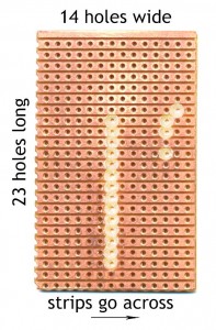
The stripboard we’re going to use should be a MINIMUM of 23 holes long (across the tracks) and 14 wide (along the tracks). This will make the board around 37mm wide and 58mm long – quite a bit smaller than a regular arduino. If you have space for it in your project, make the board bigger than this to avoid running out of space, particularly if you know you are going to need to add a lot of other components.
Cut the tracks on the board where indicated in the image below (click to zoom in) – you can use a “spot face cutter” or just a large-ish drill bit (which is practically all a spot face cutter is) for this. Use a magnifying glass or other aid to look closely to ensure that the track is completely severed. Brush away any little shreds of copper track.
POWER
First we’ll build the power supply for the board. By building in sections, this allows us to test as we go along.
Like the real arduino, we want to be able to run the board from a battery or other input with a voltage of something between 7V to 12V (we’ll also be able to run it from USB’s 5V, this won’t be via the power supply though, it’ll be via the connection to the computer — see later posts for more details).
The component that allows us to generate regulated 5V (which all our circuitry requires) from the input is an LM7805 (see http://en.wikipedia.org/wiki/78xx). The full list of components we’ll need are:
- 1 × LM7805
- 2 × 100 µF, 25V electrolytic capacitors
- 1 × 100 nF ceramic capacitor
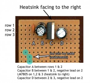
Solder them on to the board as shown in the image below (click on it to zoom in). Note that the 7805’s heatsink should be on the right. Also note the electrolytic capacitors have a polarity so need to be connected the right way around. Usually there’s a stripe down the side of the barrel showing the negative and the positive lead is longer. The ceramic capacitor (100nF) can go either way round. Position of these components can be anywhere along the strips – I’ve opted to put them in the middle.
We now already have a board that we can test. The input voltage will go to rows one and two – the top row is positive, and row two is negative. If all is working correctly, the regulated output voltage will be on rows 2 (negative) and three (positive, 5V). So to test this, I’ve temporarily soldered a 9V battery connector to rows 1 and 2. Position along the row is not important – but NOTE that if you get the polarity wrong you will fry the voltage regulator. You might want to consider incorporating a diode for reverse polarity protection, and maybe a PTC (resettable thermal fuse) for overload protection in case of short circuits. Both of these are outside the scope of this basic circuit.
Also you could consider putting an LED (with suitable resistor) across rows 2 & 3 to show that the circuit is powered on. If this is going inside a box this may not be useful!
With 9V applied to rows 1 & 2, my multimeter shows 5.04V across rows 2 & 3 as expected, and 9V (from the battery) across 1 & 2.
Stay tuned for part 2 of several, I promise they’ll be no more than a day or two apart!
Edit: Part two is now available; you can find it at http://www.martyndavis.com/?p=133


This is really good, thanks for the run through. BitBoxs to me is like the Power Tools section in B&Q… so many things, “I’ll have one of them, one of them and ten of those would be cheeper”… my wife just rolls her eyes at me now…
1 × LM805 should be 1 × LM7805
Great article though.
@coda: well spotted, thanks! I’ve changed it now.
Thanks for the work. You have put a lot of effort into this.
Hi,
When I apply a 9v battery across rows 1 and 2, I only get 4v from row 3. I tested the battery and it only gives 8v, but I don’t think that’s the problem. Am I doing something wrong? Should I use 12v instead? Thanks.
Hi Michael,
The LM 7805 voltage regulator should output a minimum of 4.8V according to the spec, so 4V is too low.
First thing to test… the LM 7805 will take an input of 7V to 25V (I’ve actually had it working OK at 6V) – you say the battery gives 8V, but I’d first check with a new battery or a regulated power supply if you can.
If it gives the same results I’d check to see what power is being drawn by your circuit – you could have a short.
If that appears normal then I’d try swapping the LM 7805 regulator for another one!
Hope this helps…
Martyn
Hi Martin
Thanks for the tutorial. I’m a complete idiot so forgive the stupid question. I’m trying to recreate the circuit and powering from the 5v pin out on an Uno. Getting just short of 5v on pins 1 and 2 but only around 1.8v on 2 and 3. Is it because I’m not giving the 7805 enough power?
Thanks
Richard
Hi Richard, yes, you are underpowering it… the 7805 needs a minimum of ~ 7.5V according to its specs. Try powering it from a 9V battery and see if things improve!
– Martyn
Hi Martyn. Thanks for the quick reply. I knew I should have paid more attention at school. Does this mean the 5v dc power supplies I’ve ordered are useless because they won’t push out enough power? Thanks – have a great Christmas
Hi again Richard, if you’ve got an external, REGULATED 5V supply, then you can dispense with the 7805 part of the circuit altogether, and simply apply the 5V to row three. Beware cheap unregulated power supplies though… their output voltage can vary wildly. Hope this helps… have a good Christmas too!