This is part two of a short series on how to build your own arduino-compatible board from scratch. You can find part one here: http://www.martyndavis.com/?p=105.
HARDWARE
Components required:
- 1 × 28-pin DIL socket (.3″ pitch) suitable for ATMega chips
- 1 × 6-pin female header
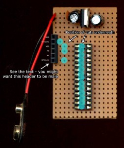
Solder the DIL socket (i.e. the socket for the ATMega chip) across the line of 14 holes we cut vertically under the board. Make sure the little notch on the end of the socket is facing up, towards the power supply circuitry. This will act as a reminder for us when we insert the ATMega chip itself. Solder the female header on the left-hand column, from row 6 down, as per the image below (click to zoom in).
The 6-pin female header (henceforth referred to as the serial connector) on the left will be the socket we use to program the device via the arduino IDE once the circuit is finished. I’ve labelled the sockets in figure 3 but you can ignore that for the time being. NOTE – if you already have an FTDI cable you may find it has a female end – you might wish to use a male header for the serial connector. I’ve chosen female as it makes it easier to hook up for burning the bootloader. If this means nothing to you don’t worry at this stage.
RESET CIRCUIT
Components required:
- Momentary push-to-make button
- 10K resistor (brown, black, orange)
- 2 × short connector wire
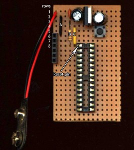
Any momentary-make button will do. Connect it so it connects rows 4 and 6 when pressed. Row 6 will be connected to row 2, so is ground. Row four will be connected to the “Reset” pin on the ATMega, which will normally be held high via a 10k resistor. Most little buttons like this have four legs, two connected pairs. Make sure you have it the right way around otherwise rows 4 and 6 will be permantly connected regardless of whether the button is pressed or not.
Connect row 2 (GND, i.e. negative) to row 6 with a piece of hookup wire – “A” in the image below.
Use the 10K resistor to connect row 3 (+5V) to the reset pin on the ATMega (row 8, left side) – “B” in the image.
Connect row 4 to the reset pin also – “C” in the image.
So it can be seen that when the button is pressed, the reset button is taken low (i.e. connected to GND) which will trigger a reset of the ATMega.
That’s the reset circuitry complete. We can’t test this yet as we have no chip inserted!
SERIAL CONNECTOR
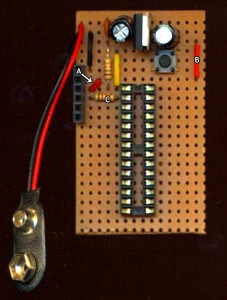
This is here so we can upload “sketches” (i.e. arduino programs) to the board. By virtue of its position on the stripboard, the serial connector (the six-pin female header we’ve already soldered to the board) is half way connected. The pins, top to bottom, are as follows:
GND (currently connected, as row 6 is GND thanks to wire “A” in the previous step)
CTS (“Clear to Send”) – not used, we’ve cut its track already
VCC (i.e. +5V) – we need to connect this.
TX – needs to be connected to the RXD pin on the ATMega via a 10K resistor
RX – connected directly to the TXD pin on the ATMega, already connected as it’s on the same row.
RTS – not connected. We’ve already cut this track.
So we need to connect VCC – we do this with hookup wires “A” and “B” in the image below.
Also we connect TX to the ATMega’s RXD pin – that’s just a question of bridging a cut we’ve already made with a 10K resistor (“C” in the image).
Once those connections are made, our serial connector is finished. Again, with no chip, we can’t test it yet.
Stay tuned… the next part is coming up in a day or so, where we’ll add a crystal to the circuit to allow the ATMega to time accurately, and we’ll make the rest of the connections. After that the interesting stuff – burning the bootloader and programming the chip with your sketches!
The next post in this series can be found here: http://www.martyndavis.com/?p=150


be sure to post a complete parts list at the end, please..
Thanks for the suggestion, I have just finished a proper circuit diagram which will have all the parts listed. I’ll post it at the end.
Mightn’t you want to run a conductor from RTS to pin 1 so the Arduino IDE can reset the Atmega? I usually do that on my breadboard / pcb arduino clones. It saves having to press the reset at a critical moment, or so I’ve always thought. Never tried it without.
@David: yes, as I mention in a later post I found this completely unreliable – it may actually be related to recent changes to the Linux serial driver from what I found elsewhere on the net, but to keep it simple I left it out. I have found that pressing reset is fine if you hold it down and let go once compilation is done. And as this circuit is only likely to be burned once or twice and then embedded somewhere it’s no hardship (to my mind) to have to reset manually. But thanks for your comment – it should be useful for people wanting to make this circuit more elaborate.